Parts Diagrams - Ford Winstar 2003 Lower Control Arm Suspension Diagrams

Posted by Blogger.com on Friday, April 13, 2012

Parts Diagrams - Ford Winstar 2003 Lower Control Arm Suspension Diagrams - new diagrams for Ford Car, here are Ford Winstar Lower Control Arms Suspension Diagrams.

Parts Diagrams - Ford Winstar 2003 Lower Control Arm Suspension Diagrams

Parts Diagrams - Ford Winstar 2003 Lower Control Arm Suspension Diagrams

1. Knuckle
2. Front hub
3. Wheel bearings
4. Lower control arm
6. Strut rod
7. Bushings
8. Strut 9. Coil spring
10. Spring insulator
11. Stabilizer bar
12. Bracket
13. Bushings
14. Link


Thanks for visiting Ford Wiring Diagrams, i hope u find what u want in here. Find more Wiring Diagrams
More aboutParts Diagrams - Ford Winstar 2003 Lower Control Arm Suspension Diagrams

Parts Diagrams - Ford Edge 2008 Edge Steering Gear Diagrams

Posted by Blogger.com

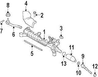
Parts Diagrams - Ford Edge 2008 Edge Steering Gear Diagrams - here are some diagrams for Ford Edge 2008 Steering Gear. I hope u can find what u want in here.

Parts Diagrams - Ford Edge 2008 Edge Steering Gear Diagrams

Parts Diagrams - Ford Edge 2008 Edge Steering Gear Diagrams

1. Gear assembly
2. Mount bolt
3. Seal
4. Upper shield
5. Lower shield
6. Outer tie rod
7. Pin 8. Nut
9. Inner tie rod
10. Retainer
11. Boot
12. Small Clamp
13. Large Clamp


Thanks for visiting Ford Wiring Diagrams, i hope u find what u want in here. Find more Wiring Diagrams
More aboutParts Diagrams - Ford Edge 2008 Edge Steering Gear Diagrams

Parts Diagrams - Ford Mustang vacuum diagrams

Posted by Blogger.com

Parts Diagrams - Ford Mustang vacuum diagrams - here are some more diagrams for Ford Car. And for these session i have some diagrams for Ford Mustang Vacuum diagrams.

Parts Diagrams - Ford Mustang vacuum diagrams

Parts Diagrams - Ford Mustang vacuum diagrams

these diagrams consist of :

1. PVS Valve
2. Temperature Controlled Vacuum Valve
3. EGR Valve
4. Normally Open Solenoid Valve
5. Normally Open Solenoid Valve
6. Spark Delay Valve 7. Check Valve
8. Distributor Vacuum Advance
9. Ambient Temperature Switch
10. Speed Sensor
12. Loop
13. Dual Area Diaphragm


Thanks for visiting Ford Wiring Diagrams, i hope u find what u want in here. Find more Wiring Diagrams
More aboutParts Diagrams - Ford Mustang vacuum diagrams

Parts Diagrams - Ford Ranger 1996 Universals Rear Axle Diagrams

Posted by Blogger.com

Parts Diagrams - Ford Ranger 1996 Universals Rear Axle Diagrams - hello, these is some diagrams for Ford Ranger 1996, these diagrams show off Rear Axle Diagrams on Ford Ranger 1996. I think these diagrams show clearly, and i hope u can find what u want on these blog post.


Parts Diagrams - Ford Ranger 1996 Universals Rear Axle Diagrams

Parts Diagrams - Ford Ranger 1996 Universals Rear Axle Diagrams

these diagrams consist of :
1. Axle housing
2. Axle cover
3. Cover gasket
4. Axle shafts
5. Shaft bearings
6. Axle seals
7. Differential case
8. Differential assembly
9. Differential bearings
9. Side bearings 10. Pinion gear kit
11. Side gear kit
12. Shaft lock
12. Shaft lock
13. Pinion shaft
14. Ring & pinion
15. Inner pinion bearing
16. Outer pinion bearing
17. Pinion bearing spacer
18. Pinion seal


Thanks for visiting Ford Wiring Diagrams, i hope u find what u want in here. Find more Wiring Diagrams
More aboutParts Diagrams - Ford Ranger 1996 Universals Rear Axle Diagrams

Parts Diagrams - Ford Fiesta Timing Belts Diagrams

Posted by Blogger.com on Friday, April 6, 2012

Parts Diagrams - Ford Fiesta Timing Belts Diagrams some diagrams for Ford Festa Timing Belts. Here are diagrams just for my beloved reader.

Parts Diagrams - Ford Fiesta Timing Belts Diagrams

Parts Diagrams - Ford Fiesta Timing Belts Diagrams

LEGEND:
fi1 Timing belt upper cover
2 Inlet camshaft toothed pulley
3 Exhaust camshaft toothed pulley
4 Timing belt
5 Timing belt tensioner
6 Crankshaft toothed pulley
7 Timing belt middle cover
8 Timing belt lower cover
9 Crankshaft pulley
10 Water pump pulley


Thanks for visiting Ford Wiring Diagrams, i hope u find what u want in here. Find more Wiring Diagrams
More aboutParts Diagrams - Ford Fiesta Timing Belts Diagrams

Parts Diagrams - Ford Taurus 2009 Engine Parts Component

Posted by Blogger.com

Parts Diagrams - Ford Taurus 2009 Engine Parts Component hi, nice to meet u again. Here are some Parts Diagrams for Ford Taurus 2009 Engine Component Diagrams. 2009 Ford Taurus X 3.5L Engine Parts and Components Assembly Diagram. The 2009 Taurus X is available in front- or all-wheel drive, and is powered by a 263-hp 3.5-liter V6 engine that is combined with a six-speed automatic transmission. Below schematic illustrates the Ford Taurus X 3.5L Engine Parts Diagram.

Parts Diagrams - Ford Taurus 2009 Engine Parts Component

Parts Diagrams - Ford Taurus 2009 Engine Parts Component

1. Cylinder head
2. Head gasket
3. Valve cover
4. Valve cover gasket
5. Exhaust valve
6. Intake valve
7. Valve seals
8. Valve springs
9. Valve spring retainers
10. Valve keeper
11. Valve lifters
12. Camshaft
13. Camshaft gear 14. Crankshaft gear
15. Timing chain
16. Tensioner
17. Tensioner arm
18. Chain guide
19. Front cover
20. Actuator
21. Rear main seal retainer
22. Pulley
23. Front crank seal
24. Oil pan
25. Oil pump
26. Oil pick-up


Thanks for visiting Ford Wiring Diagrams, i hope u find what u want in here. Find more Wiring Diagrams
More aboutParts Diagrams - Ford Taurus 2009 Engine Parts Component

Diagrams - Ford Taurus X 2008 Evaporator Parts

Posted by Blogger.com on Thursday, April 5, 2012

Diagrams - Ford Taurus X 2008 Evaporator Parts, here are some new diagrams for Ford Taurus X 2008, on these season i will give u some Evaporator Diagrams to help u. The 2008 Ford Taurus X comes with 6 different trim: SEL 4dr Front-wheel Drive, SEL 4dr All-wheel Drive, Eddie Bauer 4dr Front-wheel Drive, Eddie Bauer 4dr All-wheel Drive, Limited 4dr Front-wheel Drive, and Limited 4dr All-wheel Drive. The evaporator is mounted with the heater matrix. The evaporator creates the drop in pressure required to produce the cooling effect. It absorbs heat from the air inside the car which evaporates the refrigerant.

Here is a typical schematic describing the 2008 Ford Taurus X Evaporator Parts and Components Assembly Diagram.

Diagrams - Ford Taurus X 2008 Evaporator Parts

Diagrams - Ford Taurus X 2008 Evaporator Parts

The evaporator assembly consists of parts and components as follows:
1. Evaporator assembly
2. Evaporator mount bracket
3. Evaporator seal
4. Controller, dual zone auto AC
5. Temperature sensor
6. Expansion valve
7. Gasket
8. Inlet duct
9. Plenum
10. Vacuum motor #1
11. Vacuum motor #2
12. Vacuum motor #3
13. Wire
14. Air inlet hose
15. Blower motor
16. Retainer
17. Heater core

Thanks for visiting Ford Wiring Diagrams, i hope u find what u want in here. Find more Wiring Diagrams
More aboutDiagrams - Ford Taurus X 2008 Evaporator Parts

Component Diagrams - Ford Focus 2003 DOHC Engine Block Parts

Posted by Blogger.com

Component Diagrams - Ford Focus 2003 DOHC Engine Block Parts, here are some wiring diagrams for Ford Focus 2003 DOHC Engine, The 2003 Ford Focus come with four different body styles: a 5-door ZX5 hatchback, a wagon, a 3-door ZX3 hatchback and a sedan. The base drivetrain for all types are 2.0L dohc 4-cylinder engine. The following schematic shows the 2003 Ford Focus 2.0L DOHC Engine Block Parts and Component Assembly.

Component Diagrams - Ford Focus 2003 DOHC Engine Block Parts

Component Diagrams - Ford Focus 2003 DOHC Engine Block Parts

The engine parts and components consists of:
1. Cylinder block
2. Cylinder head
3. Head gasket
4. Valve cover
5. Valve cover gasket
6. Intake valve
7. Exhaust valve
8. Valve seals
9. Valve springs
10. Valve spring retainers
11. Valve keeper
12. Valve lifters
13. Shim
14. Exhaust camshaft
15. Intake camshaft
16. Camshaft gear
17. Crankshaft gear
18. Timing belt
19. Tensioner
20. Idler pulley
21. Front cover
22. Piston ring set
23. Piston
24. Connecting rod
25. Bearing
26. Bearing set
27. Crankshaft
28. Rear main seal
29. Rear main seal retainer
30. Pulley
31. Front crank seal


Thanks for visiting Ford Wiring Diagrams, i hope u find what u want in here. Find more Wiring Diagrams
More aboutComponent Diagrams - Ford Focus 2003 DOHC Engine Block Parts

Component Diagrams - Ford F450 2006 Super Duty Evaporator Parts

Posted by Blogger.com

Component Diagrams - Ford F450 2006 Super Duty Evaporator Parts, thansk for visiting my blog again, here are some wiring diagrams of Ford F450 2006, The 2006 Ford F450 Super Duty A/C evaporator is located inside the vehicle, and serves to absorb both heat and excess moisture inside. In the evaporator, the hot air passes through the aluminum fins attached to the tubes, and excess moisture condenses on them, and dirt and dust that carries air in turn adheres to the wet surface of the fins, then the water is drained to the outside.

The following schematic illustrates the 2006 Ford F450 Super Duty A/C evaporator parts and components assembly.

Component Diagrams - Ford F450 2006 Super Duty Evaporator Parts

Component Diagrams - Ford F450 2006 Super Duty Evaporator Parts

The evaporator system consists of:
1. Evaporator assembly
2. Evaporator core
3. Seal, evaporator core
4. Support bracket
5. Duct assembly
6. Air inlet
7. Vacuum motor
8. Blower motor
9. Seal, blower motor
10. Wheel, blower motor
11. Harness, wire assembly
12. Resistor
13. Heated air tube
14. Heater core
15. Seal, heater core
16. AC & heater case
17. Cover assembly
18. Actuator
19. Vacuum motor #1
20. Vacuum motor #2
21. Harness
22. Duct assembly

Thanks for visiting Ford Wiring Diagrams, i hope u find what u want in here.

Find more Wiring Diagrams
More aboutComponent Diagrams - Ford F450 2006 Super Duty Evaporator Parts

Wiring Diagrams - Ford Escape 2004 2L Engine Block Component

Posted by Blogger.com

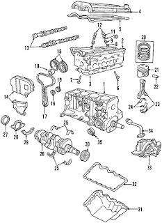
Wiring Diagrams - Ford Escape 2004 2L Engine Block Component - hello guys, check this out new diagrams for Ford Escape 2L 2004 edition. The 2004 Ford Escape comes with three different engine capacity levels: 2.0L Zetec I4; 2.3L Duratec 23 I4; and 3.0L Duratec 30 V6. The 2.0L Zetec I4 has a high 10.2:1 compression ratio; 84.8 mm (3.339 in) bore and 88 mm (3.465 in) stroke. I4 or inline-four means the engine with all four cylinders mounted in a straight line, or plane along the crankcase. The following picture illustrates the 2004 2.0L Ford Escape Engine Block Components Assembly and Parts Diagram.

Wiring Diagrams - Ford Escape 2004 2L Engine Block Component

Wiring Diagrams - Ford Escape 2004 2L Engine Block Component

The engine block parts and component assembly consists of:
1. Cylinder block
2. Cylinder head
3. Head gasket
4. Valve cover
5. Valve cover gasket
6. Intake valve
7. Exhaust valve
8. Valve seals
9. Valve springs
10. Valve spring retainers
11. Valve keeper
12. Valve lifters
13. Camshaft
14. Camshaft and timing front cover
15. Camshaft gear
16. Crankshaft gear
17. Timing belt
18. Tensioner
19. Camshaft and timing Guide
20. Piston rings
21. Piston
22. Piston pin
23. Connecting rod
24. Bearings
25. Bearing set
26. Crankshaft
27. Rear main seal
28. Rear main seal retainer
29. Rear main seal gasket
30. Pulley
31. Oil pan
33. Oil pump
34. Oil pick-up
35. Oil cooler

Thanks for visiting Ford Wiring Diagrams, i hope u find what u want in here. Find more Wiring Diagrams
More aboutWiring Diagrams - Ford Escape 2004 2L Engine Block Component

Wiring Diagrams - Ford Fusion 2006 Rear Brake Component

Posted by Blogger.com

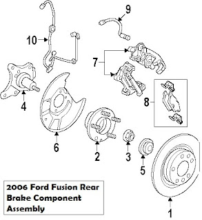
Wiring Diagrams - Ford Fusion 2006 Rear Brake Component check this out, some wiring diagrams for Ford Fusion 2006, Ford Fusion (2006 model years) comes with three different levels, S series, SE and SEL. The S series is powered by a 2.3L 4-cylinder engine (160 horsepower), while the SE and SEL are driven by a 3.0L V6 engine (221 horsepower) combined with a six-speed automatic transmission system. The main purpose of the braking system is simple; it is to slow down or stop a vehicle. The following schematic illustrates the 2006 Ford Fusion Rear Brake Component Assembly and Parts Diagram.

Wiring Diagrams - Ford Fusion 2006 Rear Brake Component

Wiring Diagrams - Ford Fusion 2006 Rear Brake Component
The rear brake components and parts consists of: 1. Rotor assembly 2. Hub assembly 3. Hub assembly seal 4. Spindle 5. Brake disc splash shield 6. Caliper 7. Brake pads 8. Brake hose 9. ABS sensor The brake pads are steel backed blocks of friction material, which are pressed onto both sides of the disc. Thanks for visiting Ford Wiring Diagrams, i hope u find what u want in here. Find more Wiring Diagrams
More aboutWiring Diagrams - Ford Fusion 2006 Rear Brake Component

Wiring Diagrams - Ford Explorer 1996 Trailer Camper Adapter

Posted by Blogger.com on Sunday, April 1, 2012

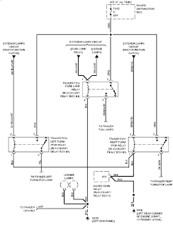
Wiring Diagrams - Ford Explorer 1996 Trailer Camper Adapter some wiring diagrams for Ford Explorer, here are check this out. The 1996 Ford Explorer is driven by 3,996 cc 4 liters 6 V front longitudinal engine with 100.3 mm bore, 84.3 mm stroke, overhead valve and two valves per cylinder. The following schematic shows the 1996 Ford Explorer Trailer Camper Adapter Wiring Circuit Diagram. This system consists of: power distribution box, exterior lamps circuit, trailer tow park lamp relay, main relay, and license lamps.

Wiring Diagrams - Ford Explorer 1996 Trailer Camper Adapter

Wiring Diagrams - Ford Explorer 1996 Trailer Camper Adapter
Thanks for visiting Ford Wiring Diagrams, i hope u find what u want in here. Find more Wiring Diagrams
More aboutWiring Diagrams - Ford Explorer 1996 Trailer Camper Adapter

Wiring Diagrams - Ford Mustang Air Conditioner Control Wiring Diagram

Posted by Blogger.com

Wiring Diagrams - Ford Mustang Air Conditioner Control Wiring Diagram The following schematic shows the Ford Mustang 5.0 Air Conditioner Control Wiring Diagram. The AC control system consists of: blower motor, blower switch, resistor assembly, compressor clutch, blower fuse, system "off" switch, WOT relay, compressor clutch, etc.

Wiring Diagrams - Ford Mustang Air Conditioner Control Wiring Diagram

Wiring Diagrams - Ford Mustang Air Conditioner Control Wiring Diagram
Thanks for visiting Ford Wiring Diagrams, i hope u find what u want in here. Find more Wiring Diagrams
More aboutWiring Diagrams - Ford Mustang Air Conditioner Control Wiring Diagram

Wiring Diagrams - Ford Mustang Drive Serpentine Belt Routing and Pulley

Posted by Blogger.com

Wiring Diagrams - Ford Mustang Drive Serpentine Belt Routing and Pulley In a car, a drive belt is used to drive multiple peripheral devices in a car’s engine, such as an alternator, water pump, power steering pump, A/C compressor and air pump. There are different types of drive belts. Cars have either a V-shaped belt, with a cross section that looks like a V, or more commonly, a serpentine belt. Below schematic shows the 2001 Ford Mustang Drive Serpentine Belt Routing and Pulley.

Wiring Diagrams - Ford Mustang Drive Serpentine Belt Routing and Pulley

Wiring Diagrams - Ford Mustang Drive Serpentine Belt Routing and Pulley
1. Generator 2. Water pump pulley 3. Belt idler pulley 4. Drive belt tensioner 5. Power steering pump 6. Drive belt 7. A/C compressor 8. Crankshaft pulley Thanks for visiting Ford Wiring Diagrams, i hope u find what u want in here. Find more Wiring Diagrams
More aboutWiring Diagrams - Ford Mustang Drive Serpentine Belt Routing and Pulley

Wiring Diagrams - Ford Excursion 2000 Power Distribution

Posted by Blogger.com

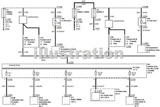
Wiring Diagrams - Ford Excursion 2000 Power Distribution hello guys, i hope u enjoy on my blog, here are some wiring diagrams for Ford Excursion 2000, The power distribution system consists of: Auxiliary Climate Control, Heated seats, Vacuum pump motor, speed control, Overhead console, Brake shift interlock (3Z719), Electronic Shift On the Fly (ESOF) solenoid, Digital Transmission Range (DTR) sensor (7F293), Clutch pedal position switch, Auxiliary Powertrain Control Module (APCM), Accelerator pedal position sensor, Overdrive cancel switch (7G550), Four wheel drive control module, Instrument cluster – Pickup.

Wiring Diagrams - Ford Excursion 2000 Power Distribution

Wiring Diagrams - Ford Excursion 2000 Power Distribution
Thanks for visiting Ford Wiring Diagrams, i hope u find what u want in here. Find more Wiring Diagrams
More aboutWiring Diagrams - Ford Excursion 2000 Power Distribution

Wiring Diagrams - Ford Falcon Ranchero 1964

Posted by Blogger.com

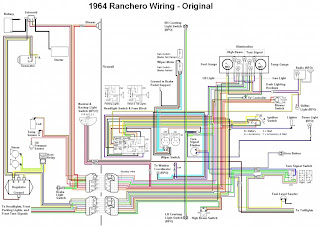
Wiring Diagrams - Ford Falcon Ranchero 1964 - nice to meet u again, here are some wiring diagrams for Ford Falcon, Back in 1960, Ford released its compact Ford Falcon line. It was a small car which was powered by a small lightweight 90 hp, 2.4 L machine with single carburetor. The 1964 Ford Ranchero wiring and electrical system schematic consists of: battery, solenoid, starter, generator, courtesy light switch, headlight switch and fuse block, blower, brake light switch, etc.

Wiring Diagrams - Ford Falcon Ranchero 1964

Wiring Diagrams - Ford Falcon Ranchero 1964
Thanks for visiting Ford Wiring Diagrams, i hope u find what u want in here. Find more Wiring Diagrams
More aboutWiring Diagrams - Ford Falcon Ranchero 1964

Wiring Diagrams - Ford Truck F250 1967 Courtesy Light Wiring Diagram

Posted by Blogger.com

Wiring Diagrams - Ford Truck F250 1967 Courtesy Light Wiring Diagram - hello guys, check this out more again for Ford Truck Wiring Diagrams, A courtesy light is a light on a car which is turn off automatically when all the door are closed or will on while a door is open. Below schematic illustrates the 1967 Ford Truck F-250 Courtesy Light Wiring Diagram. The courtesy light circuit system consists of: 9 ampere fuse panel, wiring assembly, lighting switch, courtesy lamp switch, dome lamp, and ignition switch.

Wiring Diagrams - Ford Truck F250 1967 Courtesy Light Wiring Diagram

Wiring Diagrams - Ford Truck F250 1967 Courtesy Light Wiring Diagram
21 25 37A 53 53A 53B 53D 53E 54 B-BL B Yellow Black-Orange Stripe Black-Yellow Stripe Black-Blue Stripe Black-Blue Stripe Black-Blue Stripe Black-Blue Stripe Black-Blue Stripe Green-Yellow Stripe Black-Blue Stripe Black Thanks for visiting Ford Wiring Diagrams, i hope u find what u want in here. Find more Wiring Diagrams
More aboutWiring Diagrams - Ford Truck F250 1967 Courtesy Light Wiring Diagram

Wiring Diagrams - Ford Truck F100 1967

Posted by Blogger.com

Wiring Diagrams - Ford Truck F100 1967 check this out, some wiring diagrams for Ford Truck F100, This wiring diagrams applied for 1967 Ford Truck F-100 and F-350 series. Here you will find 13 diagrams depicting the 1967 Ford Truck F-100 wiring installation including truck auxiliary tank diagram, truck courtesy light wiring, exterior lights and turn signals, truck horns diagram, ignition, charging, starting and gauging diagrams, instrument panel diagram, interior lights, instrument lights and cigar lights, truck overdrive series diagram, overdrive diagram, roof and platform marker lights diagrams, transmission system diagram, windshield wiper and wiper diagram.

Wiring Diagrams - Ford Truck F100 1967

Wiring Diagrams - Ford Truck F100 1967
Thanks for visiting Ford Wiring Diagrams, i hope u find what u want in here. Find more Wiring Diagrams
More aboutWiring Diagrams - Ford Truck F100 1967

Ford Torino Electrical System Wiring Diagrams

Posted by Blogger.com

Ford Torino Electrical System Wiring Diagrams here are some wiring diagrams for Ford Torino, The manual consists of 25 pages of PDF file type document. The wiring system include: alternator, buzzers, circuit breaker-starter, flasher, gauges, ignition coil, lamps, motors, sensors, relays, etc. Below schematic illustrates the Ford Torino Wiring Diagram and Electrical System.

Ford Torino Electrical System Wiring Diagrams

Ford Torino Electrical System Wiring Diagrams
Thanks for visiting Ford Wiring Diagrams, i hope u find what u want in here. Find more Wiring Diagrams
More aboutFord Torino Electrical System Wiring Diagrams